The conventional procedure for determining the fatigue of the specimen is a method that supposedly reflects actual stresses produced in the carrier during its useful life, i.e. the maximum service life for which the carrier has been designed or the maximum life requirement specified by a standard : to achieve that the structure of the carrier is subjected to an elevated number of stress cycles.
In this way, even though the method does not reflect the effect of environmental action, it is possible to follow up the long time behaviour of the carrier.
 Stresses to be applied during the test are specified in standards or may be derived from the results of strain gauge measurements under dynamic test conditions.
The laboratory had a special test rig built, the height of which is adjustable; it can accommodate carriers up to 6 m in height.
A 50 kN hydraulic cylinder has been fitted to the cross beam (piston stroke travel 50 mm) which produces vertical oscillations having the desired amplitude, frequency and wave shape (in most instances tests are carried out with a sinusoidal wave, which is actually the internationally adopted shape of wave for tests of the kind)
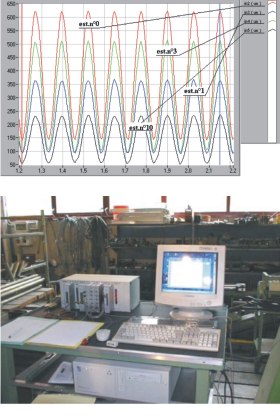
Acquisition of stress values measured in different measuring points in areas that are subjected to the heaviest stresses is by a recording device.
Tests are carried out either with fully equipped and suspended carriers, that is in real working conditions or, if need be, with carriers fixed to the anchoring rail in the floor of the laboratory.
Tests are also carried out with components of the hanger or the structural frame of the carrier without shock absorbers. Monitoring of the tested component is by means of a number of monitoring points. The hydraulic system needs to be calibrated to produce the required stresses.
The test takes quite a lot of time and test conditions are more severe than actual service conditions, but in terms of safety of the transportation system its results are by far more meanigful. In some instances the test has caused some parts of the tested component to fail thus showing details that need to be verified by the designer or given due consi-deration by the manufacturer.
The new test rig has three hydraulic cylinders, a 100 kN, a 50 kN and a 25 kN cylinder, which can able to subject the test specimen to a combination of stresses.